Information Center
Videos
Air Feed Punching and Stamping
Punching Application
Simple Demo of DIRECT-AIRE® Series
Press Fit Application
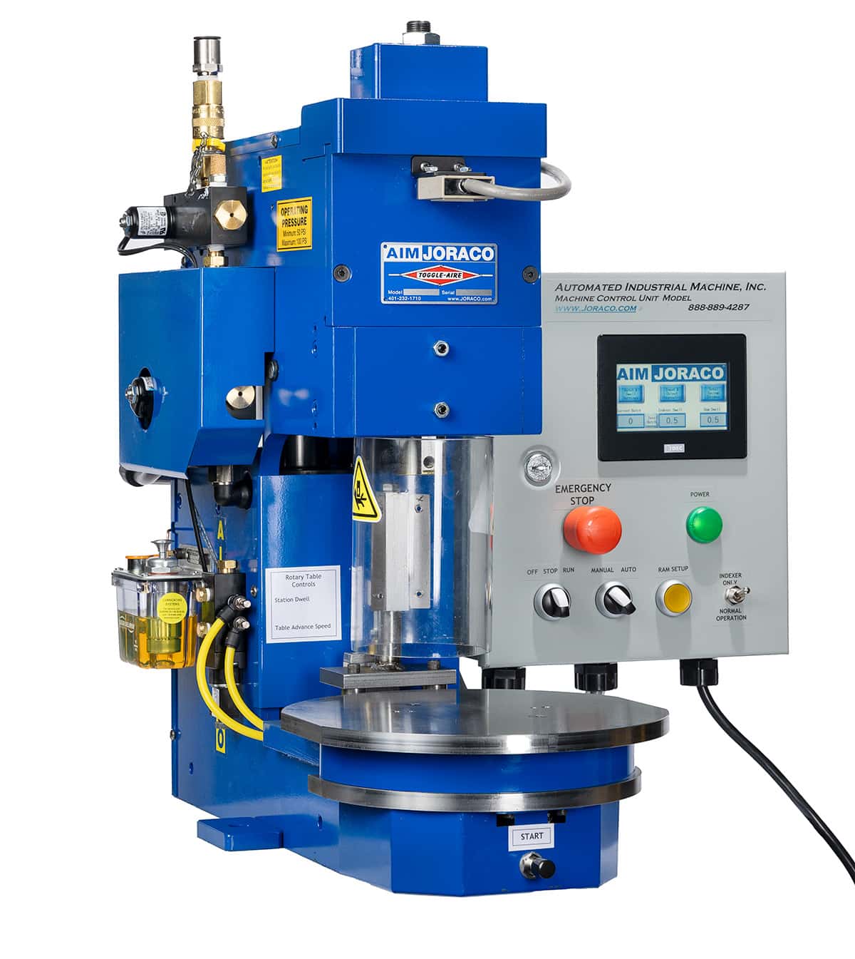
INDEX-AIRE Series Model 2000 Rotary Indexing Machine

Force Monitoring Package
Schematics and Drawings
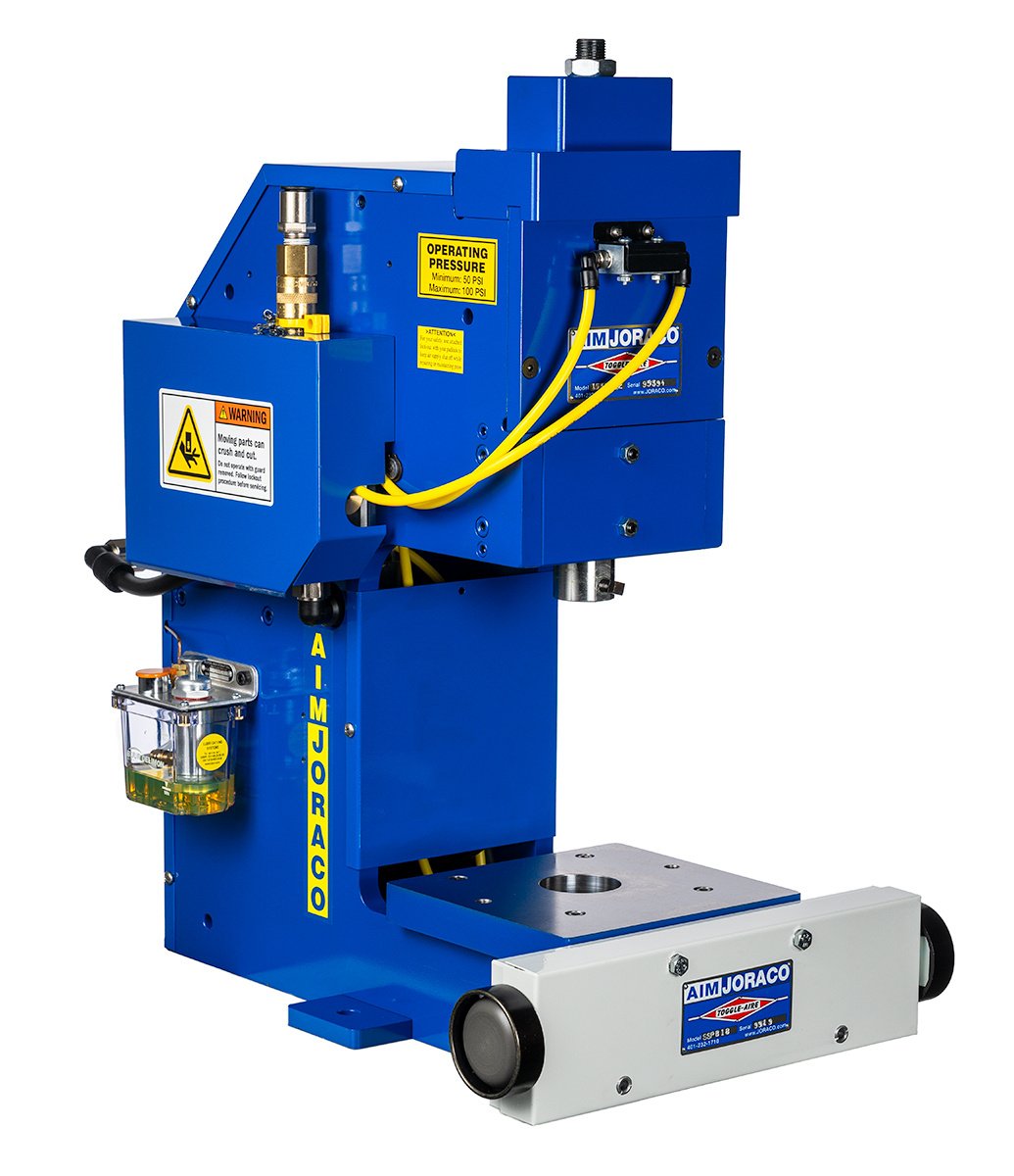
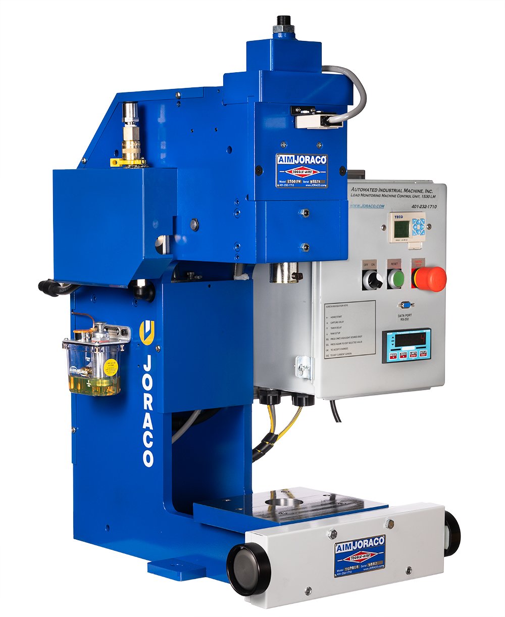
TOGGLE-AIRE® Series Model 1530
Learn More
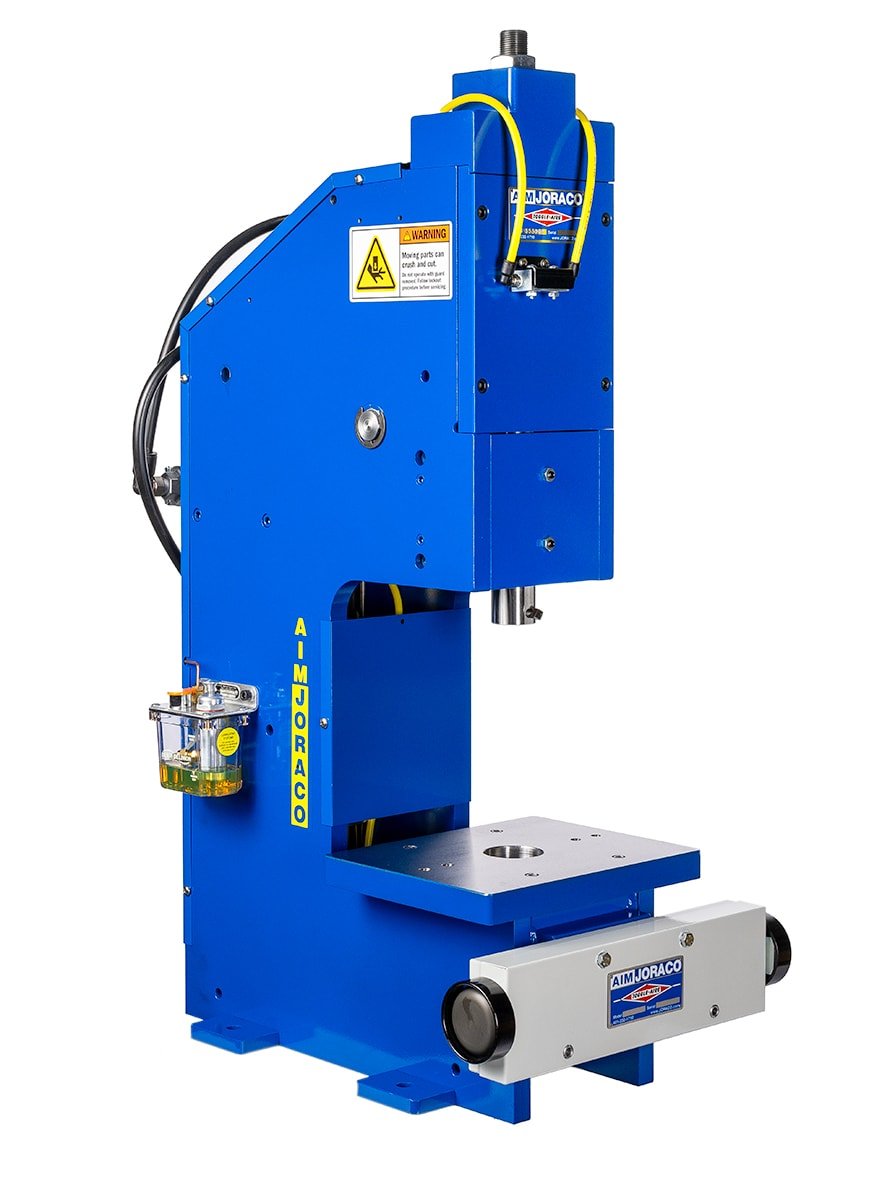
TOGGLE-AIRE® Series Model 2530
Learn More
TOGGLE-AIRE® Series Model 3530
Learn More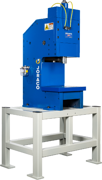
TOGGLE-AIRE® Series Model 8500
Learn More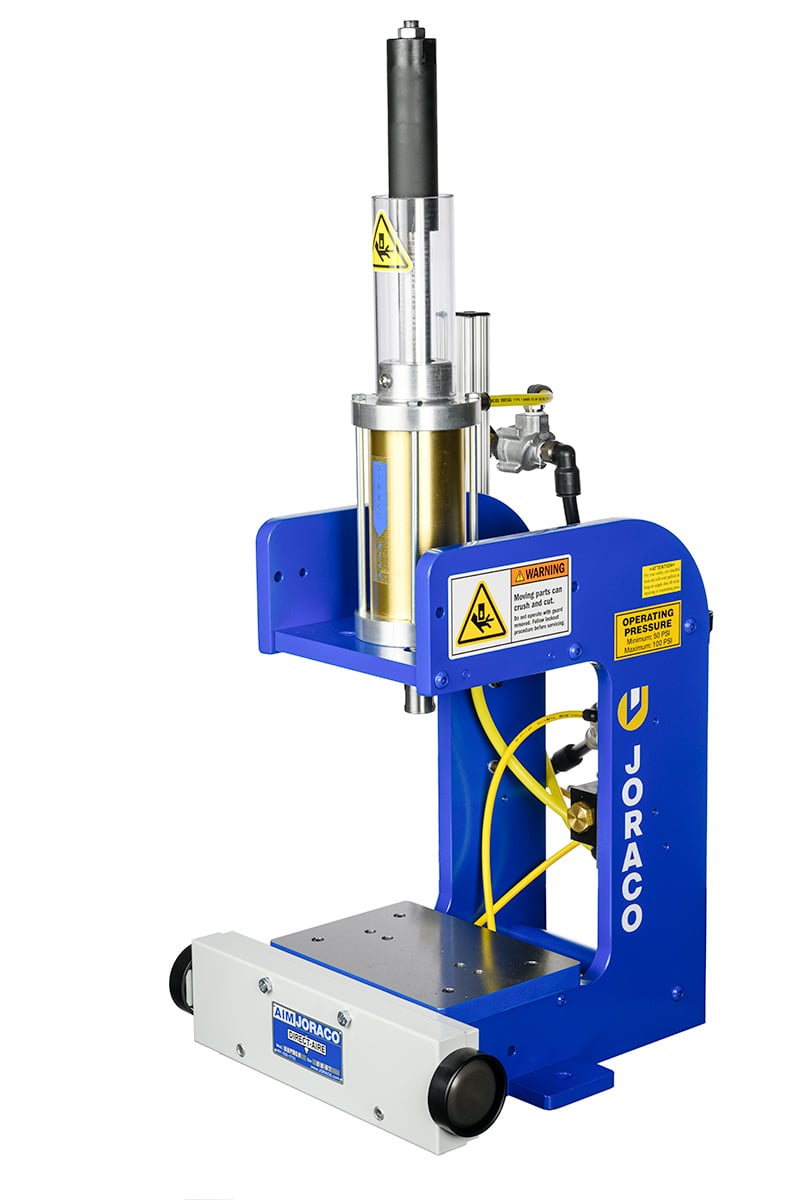
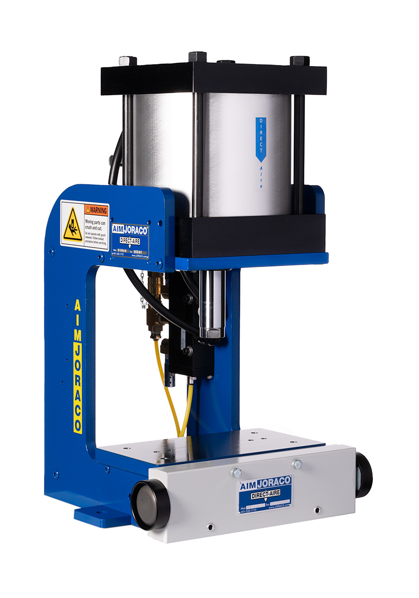
DIRECT-AIRE® Series Model 300C
Learn More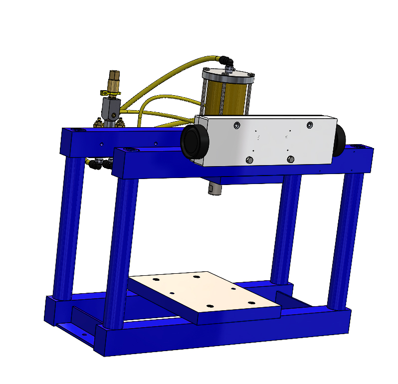
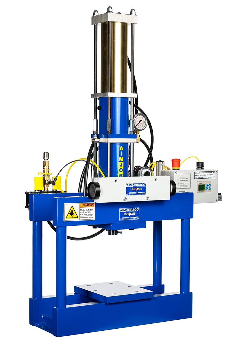
DIRECT-AIRE® Series Model 300H
Learn MoreProduct FAQs
These are our most common questions regarding Joraco Press Company's standard products. If you do not find your answer here, please refer to our Support Page.
What is a Toggle Press?
TOGGLE-AIRE® pneumatic toggle presses combine the mechanical advantages of levers and toggles. Forces produced don’t rely on ram impact; rather, it builds as the ram reaches the bottom of the stroke, and effects a shockless, powerful squeeze, regardless of ram speed. Additionally, it is highly efficient- a TOGGLE-AIRE® Series Model 1030 press is 300% more powerful than a comparable cylinder-sized DIRECT-AIRE® Series press, yet only 58% of the air is needed. Most importantly, the stroke is very precise with +/-.001” repeatability.
Why a Pneumatic Press?
Joraco Press Company presses use fully pneumatic circuitry; one connection to an air line is all you need. No clutches or brakes, no pumps, fluids, or messy leaks associated with hydraulic or mechanical presses. None of the hazards of electrical controls like shocks or sparks. And pneumatic valving systems are completely compatible with any other equipment you may be using. This flexibility plus their high power and quick response make them more suitable for today’s applications than older straight cylinder presses.
What is the difference between Shut Height and Stroke?
Shut height is distance between the ram and the bolster plate when the ram is down or “doing work.”
Stroke is the distance from shut height and full retract.
On TOGGLE-AIRE® Series press Models 1030 & 1530 the stroke is specified as 2.5”, but this is a nominal dimension because stroke changes depending on the shut height adjustment and the linkage geometry. Therefore, we don’t focus on stroke; what matters is the shut height. We can provide customers with shorter strokes on TOGGLE-AIRE® presses, but nothing longer than the specified standard stroke.
The TOGGLE-AIRE® Series Models 2530 &3530 have a standard stroke of 1.5”, but can be offered with 2” as option.
How to Calculate Force for Punching Operations
DIAMETER OF HOLE * 3.14 * THICKNESS*(MATERIAL STRENGTH in PSI) = LBS FORCE
Example: Looking to punch 0.25″ diameter hole in 0.125″ thick aluminum sheet. Material Strength for aluminum estimated at 25,000psi (25ksi)
(0.25″ x 3.14) x (0.125″) x (25,000psi) = 2453lbs ( 0.125″ thickness the force charts suggests the Model 1530 can provide 2500 to 3200lbs force between 80 and 100PSI).
However, depending on sharpness of tooling and ability of your compressor to maintain working pressure, you may decide to select the Model 2530 as it provides a larger working range. Being a toggle press, it provides a reaction force up to the max capacity of the machine. So, the Model 2530 would offer more flexibility, minimizes wear on the press components, and won’t damage your parts due to the nature of reaction forces.
You will then need to refer to press force charts (found with each press model), for press based on material thickness to determine correct model.
Force Monitoring Options: Closed Loop vs. Force Triggering
The closed loop FM-CL package will allow for data logging via the MS excel spreadsheet which can/will allow for record keeping data/QC if this is needed. This system also provides monitoring of the pressure in the system as well to always ensure the correct force is being applied to the part. If they do an outside form of inspection/QC then the FM package would be sufficient it will still provide them with data logging via the MS excel spreadsheet. Both provide an accurate measurement of force via a load cell. The FM package includes only a load cell that is calibrated to a given engineering unit and provides no compensation or monitoring to the pressure in the system, hence the non-closed loop. With the FT package this will provide a basic pressure monitoring system, which if mathematically extrapolated can provide you with a given force of the system. All the systems will provide an accurate force over a given pressure range. However, If they need a full feedback (IE: displays/readouts/data logging/force via a load cell) the FM-CL would be the best option. If they need to press to a given engineering unit with minimal feedback (IE: data logging/force via a load cell) the FM package would be suitable. Inversely if they need a price conscious system that provides the basic mathematical force with no feedback (IE: pressure monitoring only) then the FT package will suffice.
When do I need the ASH- Adjustable Stroke and Hard Stop Option?
The ASH (Adjustable Stroke and Hard Stop) is an optional feature offered on our DIRECT-AIRE® Series presses. You may be able to perform your operations without this feature by simply placing stop blocks (block of steel) between the ram and bottom plate to stop the ram from entering too deep into your parts. Our ASH utilizes a common piston shaft with a ram protruding from the top with an adjustable collar for depth setting.
What is the FRL– Filter, Regulator, & Lubricator?
The FRL is an essential component to long trouble free operation of any pneumatically operated device. The FRL cleans the air and supplies lubrication to the internals of the valving and seals, as well as offering adjustability of pressure. This is offered as an option since facilities/ operation managers have a preference on how they maintain their air supply systems – dryers, condensers, FRL, etc.
Setting up your FRL? Click Here: FRL FAQ
What is the NR, Non-Rotating Ram, and what purpose does it serve?
In DIRECT-AIRE® Series Presses- just as on older units, the piston is free to rotate inside the cylinder unless there is a mechanism designed to stop possible rotation of the ram. In some applications it’s not a concern – such as having a simple flat on the ram that is used to press fit components – in such application the ram rotation has no impact on the operation – however, if an application was to punch a shape such as a square – you would not want rotation to occur as it would destroy the tooling and offer inferior quality parts.
What is the SV, Tooling Set-Up Valve, and what purpose does it serve?
The Set-Up Valve is the small toggle switch feature located at the back of DIRECT-AIRE® Series presses – when flipped on, it activates and holds the ram to the down position. When flipped off – ram returns up. This feature is used for setting tooling to the proper depth more value ad
What are the ways that TOGGLE-AIRE® Series presses can be controlled?
1. BEM Impulse Mode.
In operation, this control method requires momentary actuation of the Synchro-Sig Anti-Tie Down Two-Hand Controller (SS-PB) unit to initiate the press cycle. Once the press has been activated, the ram will descend until it reaches the bottom of the stroke where the linkage stops against a positive stop before the press will reverse. The ram will not return up until it reaches maximum strength and travel. The BEM Impulse mode of operation insures a very accurate stroke and helps guard against inattention of the operator, loss of air pressure, improper loading etc., and maintains the quality of the work being performed. Repeatability in this mode is plus or minus .001″
2. CSR-G2 (Constant Signal Required Mode, Version 2) CURRENT STANDARD CONFIGURATION
This method of control requires that the operator’s hands be held down on the SS-actuator for the full duration of the down stroke of the press. If one or both hands are removed before the press ram reaches bottom the ram will instantly reverse and return to the top of the stroke and await a new signal from the two hand unit. This method of operation is especially useful in applications requiring slow ram speeds or special loading considerations. As the standard configuration, operators are told to keep both hands on the controller until the press automatically cycles. Once the ram has bottomed, it will automatically reverse and retract, insuring a complete and accurate part, while maintaining a safe operation.
3. SAR Stall Activated Reverse.
In this method of control the press ram reverses automatically as soon as it stalls, regardless of its position relative to the bottom of the stroke. It is quite useful in coping with tolerance variations of parts to be assembled, die castings, etc., as the ram does not have to reach absolute bottom before it will retract. it is important to remember that this can be used only if you have established that the press will have enough power to do the job in question throughout the full range of your parts, that is, both ends of the tolerances. See the RAM FORCE tables for each model to determine how much power you will have at your disposal. The SAR Stall Activated Reverse Mode is also very useful in delicate jobs. By playing the air supply pressure against the depth setting of your tools you can, in effect, reverse the press when a desired maximum force has been developed and create a very delicate stroke which will not damage fragile parts, etc.
4. CSR (Constant Signal Required)
This standard method of control for our DIRECT-AIRE® Series presses means the ram stays down as long as the operator keeps their hands on the controller. When removed, it retracts.
Technical FAQs
These are our most common technical questions regarding Joraco Press Company's standard products and presses in general. If you do not find your answer here, please refer to our Support Page.
Air Pressure and Volume – What do I need to know?
What are the Suggested Lubricating Oils for TOGGLE-AIRE® and DIRECT-AIRE® Pneumatic Systems?
For Pneumatic Systems – Air tool oils with an ISO Grade 32 Non-detergent recommended. Note: Compounded oils containing graphite, fillers, etc. are not recommended for use with air line lubricators. Fire resistant oils containing phosphate esters should not be used with polycarbonate lubricator bowls. SMC-FRL Units
What are the Suggested Lubricating Oils for TOGGLE-AIRE® One-Shot Lubrication Systems (OSL)?
For Pivot Points and Rams (One-Shot Lubrication System (OSL) or Manual Oiling): SAE 20 or 30 Single Viscosity Non Detergent Machine Oil Class 2 Viscosity 100-200 S.S.U.@ 100F deg., minimum aniline point or 200F deg.
Is the Bolster Plate Removable?
Yes. It is not welded. The plate is bolted and can be modified to allow parts to drop through. The opening under the bolster plate is 5″ x 5″.
Why does my Model 2000 NOT cycle when Start Button is pressed?
First check to be sure the batch counter is not full, turn OFF Batch Count or Reset Batch Count. If machine still not operating, be sure the machine is in RUN Mode, Ram Setup is OFF, Switch is in Normal Operation, Power Machine OFF/ON and try again. If still not operating, check I-7 on Diagnostics Screen – when power reset occurs – I-7 should be “ON” . If not, sensor needs to be adjusted. Turn AIR OFF – Remove Tooling Plate, sensor located on index unit at “4” o’clock position. Adjust IN or Rotate until Amber lit pickup on crest of station lobe. Turn machine Off, supply air Power on test. If OK, Turn OFF AIR – re-attached tooling plate and proceed to normal operation.
I am using the Two-Hand, Anti-Tie Down Controller (SS-PB) – But the Press Does Not Cycle. What do I do?
Items to check if you have a press running fully pneumatic with the a Two-Hand, Anti-Tie Down Controller (SS-PB) – CLICK HERE
Can you please explain the Force Chart?
The displacement increments are DISTANCE FROM BOTTOM OF STROKE – I.E. – if you need to push a bearing into a pocket and the push distance is 0.5” then the force chart is telling you at the beginning of the push(0.5” up from end of stroke) the press can only generate 945lbs of mechanical leverage at 80psi to start the push at that height. So if the push force required for the bearing is more than that, the this particular press model doesn’t have enough starting force to do the job and the press will stall out.
Press “max” force is rated .020” from end of stroke- When the ram is in the down(closed) position. This force is not affected by shortened strokes, as the end of stroke reference stays the same, it’s simple the retraction of the stroke that is limited.
The force/leverage that the press can obtain follows an exponential curve similar to a mechanical flywheel crank. Force at end of stroke is always the MAX force capable of being achieved by the press as the linkage/toggle is opened to optimal mechanical leverage. The advantage of toggle presses – – highly repeatable to the end of stroke depth that is adjustable via the shut height– and develops a “squeezing” force that is controllable and accurate vs a standard air cylinder style press or hydraulic press that just applies force via impact.
Video of toggle action: https://www.joraco.com/support/videos/toggle-aire-press-animation/
In conclusion -A toggle press should always be working to end of stroke. – Additionally, our TOGGLE-AIRE® Series presses provide feedback via CSR-G2 – which requires the operator in a manual setup to maintain hands on the two-hand controller; when the end of stroke is reached, the press will auto -retract – giving the feedback that the cycle was completed to the correct depth. If the press does not return, this is an indication that the shut height was set too deep. In an automated setup – the signal is sent to fire the press, and the end of stroke switch provides the feedback to PLC to say the work is complete, to remove signal and allow press to retract.
How do I calibrate my Force Monitoring Press?
DESCRIPTION:
Joraco FM-FS Presses incorporates a programmable force set value, (as well as a ramping function). Which is set with the TECO PLC Controller. The TECO PLC Controller converts the desired engineering units to a voltage signal which sets the air pressure of the electronic SMC unit located in the back of the press. This unit has a RED digital displace showing the pressure (psi) the unit is set to. When the press reaches end of stroke, the RDP Force Monitoring Unit reads force (lbs) and compares to the setpoint limits for Good Part/Bad Part.
L1 is the lower limit threshold value. L2 is the upper limit threshold.
If lower limit is NOT reached – unit reports BAD Part
If lower limit AND upper limit are reached – unit reports BAD Part
If lower limit is reached, but NOT the upper limit – unit reports GOOD Part.
Accessing MENUS:
MENU OVERVIEW:
TO ACCESS A MENU FROM THE UNIT’S NORMAL OPERATING MODE, PRESS THE SETUP KEY FOR
AT LEAST ONE SECOND. THE DISPLAY WILL SHOW THE PROMPT [UL 1]. PRESS THE ▲OR ▼
KEY TO STEP THROUGH THE VARIOUS OPTIONS, WHICH ARE:-
DISPLAY ACCESS
[UL 1] USER SETUP MENU
[UL 2] CALIBRATION AND USER SETUP MENU
[UL 3] CONFIGURATION, CALIBRATION AND USER SETUP MENU
WHEN THE REQUIRED USER LEVEL IS DISPLAYED, PRESS THE LIMITS KEY TO SELECT THE
DISPLAYED OPTION. THE DISPLAY WILL NOW SHOW A NUMBER ENTRY PROMPT [00000] WITH THE
LAST DIGIT FLASHING. AT THIS POINT THE RELEVANT PASSWORD SHOULD BE ENTERED
SETUP INSTRUCTIONS: LIMITS
SETTING LIMITS:
Enter UL1, (Password 00001) as you scroll through the menu:
[Filter] DO NOT CHANGE – FACTORY SET
[Count] DO NOT CHANGE – FACTORY SET
[L1-2] Press Enter
LIMIT L 1-2
LOWER LIMIT SETTING:
L1 ON
[HI] HIGH. The limit activates when the input signal is higher than the set point.
Function : n-IP
SETPOINT – Value the limit needs to reach to trigger.
[Lat.N] Latching NO
UPPER LIMIT SETTING:
L2 ON
[HI] HIGH. The limit activates when the input signal is higher than the set point.
Function : n-IP
SETPOINT – Value the limit needs to reach to trigger.
[Lat.N] Latching NO
When screen cycles back to L1 – press RESET to exit, [run] press ENTER.
SETUP INSTRUCTIONS: FORCE / LOAD CELL
CALIBRATION OF LOAD CELL:
Enter UL 2(Password 00002) as you scroll through the menu:
[dP] DO NOT CHANGE – FACTORY SET
[CAL.IP] press ENTER.
00000 press ENTER to move along Digit. PRESS THE ▲OR ▼ to change value
Once last digit is assigned value: example 26000
Press ENTER & RESET at the same time to accept the cal value.
Screen value will change
Press MODE & ZERO at the same time to clear previous Cal.
Screen value will change
REMOVE LOAD from PRESS (Apply Zero Load)
Press ZERO
On the TECO PLC Screen Press the Down Arrow to enter Ram setup Screen.
Press Two Hand Controller to Apply Force.
With the RAM Down.
Press SETUP (Sets New Calibration value to the applied force)
Press MODE & SETUP at the same time
[E.OFF] Exit Calibration – Press RESET.
Exit RAM only mode on TECO PLC to retract Ram .
Operate press normally. Confirm calibration. Repeat if necessary.
TROUBLESHOOTING:
HP-30 Example (30 Ton Press)
30T * 2000lbs = 60,000 lbsF at 100psi(100%)
60,000 / 100psi = 600lbs/psi reading
If Force set to 26,000 lbs the SMC unit should read 43.
26,000/60,000 *100 = 43.
SMC: Force
100 60,000
75 45,000
50 30,000
25 15,000
Calibration Accuracy +/- 2% (+/- 1200lbs)
If variation in readings are occurring – it is important to note that the positioning of the tooling, the attachment point of the load cell, and any variability in the fixturing will affect the readouts.
It is recommended to perform a calibration verification using the ram setup feature on the Teco PLC unit to compare the input/output readings. If different by more than Calibration Accuracy, before performing a calibration, inspect the fixturing, tooling and load cell mounting plate are secure. Any variation in their locations will change the output reading.
It is recommended to calibrate the system to the force range you are working within for best results.
LoadCell:
The loadcell is very sensitive and delicate. The loadcell ram assembly should be secured to top of tooling fixture or die set. This will ensure the load cell and wiring do not twist or result in damage. Securing the tooling offers the best results in data readout, capture and consistency.